


Recently, during the project, there was a need to implement a system that was meant to signalize whether it is a phase or not. And that the system output signal is acceptable for the microcontroller.
I have considered a few options that I’ll show below.
It should be remembered that in the presented systems there are voltages that are dangerous to life or health, so having no adequate experience should not be performed without supervision of a person with appropriate experience and privileges.
230V AC Coil Relay
The most easiest solution is a 230V AC relay.

In this way, when a phase voltage is present, the relay contacts will be connect. Thanks to the pull-up resistor on the output we get 5V or 0V.
Advantages:
- simply
- Galvanic separation
Disadvantages:
- Relatively large size
- Generates noise
- Possible mechanical damage
- High price
Bulb and Fotorezystor
Another simple way would be to supply a small bulb that will light up the fotorezystor.

It would be good to close the system in a box so that other light sources do not interacted on the fotorezystor. The layout is probably even simpler than the previous one. Fotorezystor together with the serial resistor creates the voltage divider. Provided that the bulb will be lit with full effect, or at all, it’s on the output of the system we will have 5V or 0V.
Advantages:
- Galvanic separation
- Quiet working
- Low price
Disadvantages:
- Relatively large size
- The system emits heat
- Possible mechanical damage
Neon and Fotorezystor
Simple modification of the previous layout and instead of the bulb we give neon bulb with a suitable resistor.

Advantages:
- Galvanic separation
- Quiet operation
- Low price
- Very low energy consumption
Disadvantages:
- Relatively large size
- Possible mechanical damage
Optocoupler
This is a more electronic solution, it uses the same concept as the previous, but are here all closed in one factory housing, so we have smaller size of the whole system, and more confidence in the working environment.

R1 resistor series with diode is the task of limiting current, and R2 is a standard pulling resistor.
In this system, however, we do not get what we want. It could be called a zero detection system. It is well explained by the following oscylogram showing the output signal during the presence of the phase:
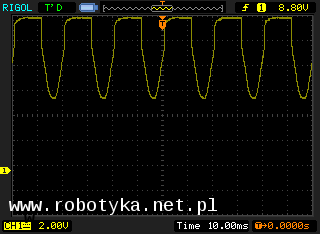
The modification we can do to exploit the satisfactory effect is to set the capacitor, which smoothes this signal:

And below the effect of the modification. We have constant voltage acceptable by microcontrollers.

Advantages:
- Galvanic system separation
- Quiet operation
- Low price
- Very low energy consumption
Disadvantages:
- Possible electronic damage
Summary
Browsing the internet for ideas on the layout several times came up with the simplest solution that may be, that is, a normal power supply which at the output has a 5V. But it is a solution not optimal in all respects, for this very much advise against it.
As you can see in the examples attached, you may be able to approach the problem in different ways, but be aware of one. In systems where the hight voltage is present, they must be galvanically separated from the rest of the system. Personally, I will always use the solution with optocoupler, due to the low power consumption, the small cost of the components, and the certainty of working conditions.